

Eva Zezulová
Branislav Dubec
Branislav Dubec
Petr Dvořák
Petr Dvořák
Josef Fládr
Josef Fládr

2 and
Klára Cibulová
Klára Cibulová
Faculty of Military Technology, University of Defence, 662 10 Brno, Czech Republic Faculty of Civil Engineering, Czech Technical University in Prague, 166 36 Prague, Czech Republic Author to whom correspondence should be addressed. Buildings 2023, 13(12), 2963; https://doi.org/10.3390/buildings13122963Submission received: 9 October 2023 / Revised: 24 November 2023 / Accepted: 26 November 2023 / Published: 28 November 2023
(This article belongs to the Section Building Structures)Plastic spacers create a linear and systemic weakening of the structure. The extreme loading of the structure tests the structure itself to its load-bearing limit or even locally exceeds this limit, thus revealing all its weak points, which are the spacers. Nevertheless, the influence of the spacers is not included in the design calculation of the reinforced concrete element. In addition, products intended as spacers for the placement of reinforcement do not belong to the specific families of construction products covered by a harmonized standard of European parliament regulation. For these reasons, it is not required to demonstrate any characteristics of these products. This fact allows the use of arbitrary spacers’ shapes and materials. As shown by the experiment carried out, the use of commonly used plastic liners will result in a weakening of the cross-section. The normal assessment of the ultimate or serviceability limit state is not affected by this weakening. An example of an experiment carried out where this problem was captured is the subject of this paper. With Europe’s current deteriorated safety situation, understanding the influence of spacers in blast-loaded reinforced concrete structures on structural failure is important, and it is appropriate to further address this issue. Based on this experiment, it is not possible to accurately identify the causes of the explosion cracks. In order to determine with certainty the effect of spacers on the strength of the structure under abnormal blast loadings, research needs to focus on this area. In the field experimental measurements and numerical simulations, it was found that the use of linear spacers has an effect on crack formation under the blast action of the tested slab.
After a long period of relative security, Europe is facing a deteriorating security situation. The security situation has deteriorated in all respects, including the military aspect. For this reason, the protection of critical infrastructure is a key task for the preservation of the functioning of states. Concrete is one of the key materials used for the design and construction of both the critical infrastructure facilities themselves and the facilities used to protect critical infrastructure elements. The results of experimental investigations of blast-pressure wave effects on reinforced concrete structures provide important input for refining the mathematical material model and for the process of designing reinforced concrete structures with the assumption of extraordinary loading by rapid dynamic action [1,2,3].
The correct function of the reinforced concrete structure is ensured by the appropriate position of the reinforcement in the cross-section of the concrete element [4]. The reinforcement shall be designed in the direction of tensile stress and as close as possible to the tensile edge. To ensure the durability of the entire structure, it is always necessary to ensure the distance of the reinforcement from the surface, the so-called cover layer of steel reinforcement.
This layer prevents the steel members from being exposed to the surrounding environment. Exposure of the steel members to the open environment causes corrosion and consequent reduction of the cross-section of the member. Corrosion of concrete reinforcement occurs when it occurs in concrete with a pH value of less than 9. Newly made Portland concrete has a pH value between 12 and 13 [5]. These concretes thus provide sufficient protection against corrosion. However, due to the influence of airborne CO2, this value gradually decreases from the surface of the structure to its core. This process is very slow, and placing reinforcement bars, e.g., 20 mm below the surface, will provide decades of protection for the reinforcement.
Another adverse effect of a conventional reinforced concrete structure is fire. The high temperatures that arise during a fire penetrate the surrounding structures, which become significantly hotter even if they do not burn. Exposing a reinforced concrete structure to high temperatures is particularly dangerous for the steel reinforcement, which loses its mechanical properties when it reaches 400 °C [6]. For the reinforced concrete structure to be safe even during a fire, it is necessary that the concrete again protects the steel reinforcement sufficiently. For example, for load-bearing columns, a cover layer thickness of between 40 and 70 mm may be required due to fire.
As can be seen from the previous two examples, the position of the reinforcement must be accurate for the proper functioning of the reinforced concrete structure. To fix the position during concreting, so-called spacers are used, which, by their presence, make it impossible to approach the formwork. Spacers are most often made of fine-grained concrete or plastic. The advantage of using concrete elements is that there is no significant weakening of the structure at the location of the spacer after the structure has been concreted. Concrete spacers are much more expensive than plastic elements, which is why plastic elements are most used.
Plastic spacers create a linear and systemic weakening of the structure and are designed so that the concrete will flow underneath them during the actual pouring of the concrete, and once the concrete has set, the strips themselves are no longer needed. This hypothesis is only correct for normal use of the structure; however, this is not the case under extreme loads (fire or explosion). In extreme loads [7], the structure tests the structure itself to the limit of its load-bearing capacity, or if locally, even exceeds this limit and thus reveals all its weak points, which are the spacers. An example of an experiment carried out where this problem was captured is the subject of this paper.
In the design of reinforced concrete structures, the influence of spacers is not included in the calculation, although their influence on the quality of structures has been published in [8,9,10,11].
In the article [8], the effects of spacers on mass transport and the microstructure of concrete were studied. In total, 140 samples using plastic, cementitious, and steel spacers were investigated. These samples of various cover depths, aggregate particle sizes, and under different curing ages and conditioning regimes were tested. The paper concludes that plastic spacers exhibited the most elevated porosity at the interface between the spacer and concrete. Across all measured properties, samples with plastic spacers demonstrated the poorest performance. This is likely attributed to a fragile bond between the plastic material and concrete. Additionally, there is a more pronounced disparity in material properties concerning drying shrinkage and thermal behavior [8]. Considering the size of the tested samples, plastic A-shaped wheel and tower spacers were preferred to linear or bar spacers. Based on the above, it can be assumed that the test results for the linear spacers used in our RC slabs would show even worse results.
The paper [9] also studied the spacer–concrete interface using 216 cylindrical test samples containing plastic A-shaped spacers and cementitious spacers. Specifically, it investigated how the addition of supplementary cementitious materials, such as silica fume or fly ash, which are used in modern concrete mixes, could decrease the negative impact of the spacers. It is concluded that in some cases, the use of supplementary cementitious materials may mitigate the negative impact of spacers, but not in the samples where plastic spacers are used. Moreover, samples featuring plastic spacers displayed pronounced gradients in porosity and the presence of cracks, indicating debonding at the interface between the spacer and concrete [9]. According to Table 1, the concrete mix design for our RC slabs does not contain any supplementary cementitious materials, so it is assumed that in the case of their use, there would be no significant improvement in the spacer–concrete interface in the slabs.
The research presented in [10] investigated the spacer–concrete interface in reinforced concrete columns with plastic or cementitious spacers under a 50 mm cover. The specimens obtained from the columns underwent testing with respect to several variables, including sample position, compaction frequency and duration, spacer type, and the conditioning regime. The article states that plastic, characterized by a smooth, non-porous surface, does not promote adhesion to concrete. Additionally, the thermal expansion coefficient for polyvinyl chloride, used for plastic spacers, is approximately 10 to 15 times higher than that of concrete [10]. A crucial finding for our tests is that, despite perforation of the plastic spacers by more than 25% of their gross plane area to alleviate these adverse effects, microcracking still occurred.
The article [11] investigated the corrosion of three pre-cracked concrete beams that were part of a larger test after 25 years of exposure to atmospheric, tidal, and seawater conditions. The plastic spacers, with 25 mm of cover, were used to keep the reinforcement in place during the casting of the beams. The research focused on the overall state of the corrosion of the beams, chloride and moisture content, and resistivity measurements. During the investigation, where some plastic spacers were exposed to saline water, high corrosion was observed, and it was attributed to the inhomogeneous and porous microstructure of the plastic spacers. In conclusion [11], it was hypothesized that corrosion at the weakest link, represented here by the highly exposed reinforcement at the plastic spacers, protects the steel in other areas, including cracks.
These are relatively new articles from 2016 onwards. These articles confirm their conclusions that spacers have a negative effect on the homogeneity of concrete elements, which weakens the concrete elements. This weakening is caused by insufficient wrapping of the contact between the reinforcement and the spacers and by the porous interface between the spacer and the cementitious mixture; for more weakening, it goes through the entire cover layer of concrete. The effect of this weakening is to reduce the chemical [8,9,10,11] and mechanical durability of those elements. As described in the articles [8,9,10,11], the negative effect of the spacers on the mass distribution was due to the preferential flow through the pores and microcracks formed at the interface between the spacers and the concrete [9]. In the long term, this results in increasing the risk of premature corrosion or degradation of the surrounding concrete. This effect is not currently recognized by most researchers or practitioners.
Discontinuities in the material at the interface of the spacer, steel reinforcement, and concrete also have a major influence on the mechanical properties of concrete structures. When the structure is loaded with fast dynamic actions, these are the exact places where cracks will develop.
In addition, products intended as spacers for the placement of reinforcement do not belong to the specific families of construction products covered by the harmonized standard Regulation No 305/2011 of the European Parliament and of the Council [12]. For these reasons, it is not required to demonstrate any characteristics of these products. This fact allows the use of arbitrary shapes and materials. As shown by the experiment carried out, the use of a commonly used plastic spacer will result in a weakening of the cross-section due to the plastic spacer.
The research on the effect of spacers on the mechanical properties of blast-loaded reinforced concrete slabs is unique in the scientific community. Research of sources has found only a limited number of articles that discuss this negative effect.
The reinforced concrete (RC) was produced as a reference material to the two sets of specimens made of steel fiber reinforced concrete (SFRC) and ultra-high-performance steel fiber reinforced concrete (UHPSFRC), used for the Experimental Campaign to Verify the Suitability of Ultrasound Testing Method for Steel Fiber Reinforced Concrete Fortification Structures, published in [13,14,15]. The recipe for 1 m 3 of mix is given in Table 1.
The slabs, with dimensions of 700 mm × 700 mm × 60 mm of the batch marked A3, are made of reinforced concrete of strength class C 50/60 (RC), reinforced with a steel mesh of B500A Ø6/100 × 100 steel placed in the area of the neutral axis of the cross-section. (Figure 1). The fixing in the required position is ensured by a D-rail spacer, DISTECH IV, 20 mm high. The tested slab is a scaled-down structural element; for example, a ceiling slab or a foundation slab. These structural elements are reinforced with steel mesh, and the thickness of the cover layer is defined by spacers of different shapes. These structures are used for critical or defense infrastructure, which should be designed for the effects of blasts.
In addition, accompanying standardized solids were produced from each batch of concrete to verify the material properties of each concrete formulation. The test specimens were manufactured and treated in accordance with EN 12390-1-5 [16,17,18,19].
The compressive strength of the used reinforced concrete mix was determined on 150 mm × 150 mm × 150 mm test cubes from concrete aged 28 days, Table 2, and the flexural strength was tested on 100 mm × 100 mm × 400 mm test beams, with the results noted in Table 3.
Before the actual experimental measurements, a numerical simulation of slab loading was performed at the Department of Engineering Technology in the LS-DYNA software environment. Based on this simulation, the appropriate amount of explosive (375 g of TNT for the A3 batch) was calculated to achieve the desired crack development but not to break the slab. The goal of the simulation was to create only hairline cracks in the slab without total slab destruction. The amount of explosive for the A3 batch slabs was determined to be 375 g of TNT.
Based on the determination of the TNT explosive quantity, a load plan for each slab was drawn up (Table 4).
To simulate the blast loading of the structure, an improvised test structure was chosen to simulate the action of the test slab in a real structure by supporting the slab along the entire perimeter, and the explosive was suspended above the slab at a distance of 580 mm (Figure 2). The test structure was assembled from a precast reinforced concrete socket foundation [13]. This stand-off distance of the explosive from the slab was chosen in accordance with the assumption, based on experience with the blast loading of reinforced concrete structures, that the blast will cause ray-like crack development on the reverse side of the slab from the blast due to slab deflection without partitioning the slab into multiple fragments. The initiation of the explosive at this stand-off distance also allowed the loading to affect the slab that was more homogenous over its whole surface due to the spherical propagation of the blast wave than any shorter stand-off distance initiation of the explosive [13]. Despite this assumption, the failure of the reinforcement occurred at the spacers, which was demonstrated in the radiographic images and is presented in the next chapter. The rest of the test structure was assembled from a precast reinforced concrete socket foundation, where a complete description can also be found in [13].
Based on experience with blast loading of reinforced concrete structures, the assumption was that the ray-like crack development on the reverse side of the slab from the blast was due to slab deflection [13]. However, the failure of the reinforcement occurred at the spacers, which is demonstrated in the radiographic images.
The radiogram of the A3_1 RC slab loaded with 350 g TNT (Figure 3) demonstrated that only the more significant cracks are visible and are highlighted on the radiogram. There are more visible cracks on the slab itself than could be observed on the radiogram. On the other hand, the steel mesh reinforcement and the horizontal reinforcement spacers are significantly visible on the radiograph. In Figure 1a, the placement of the spacer and the steel mesh in the mold to produce A3 batches is visible. The relative position between the steel mesh and the liner is secured by a tie wire. Therefore, the spacer was exposed to the blast before the steel mesh.
The radiogram of the A3_2 RC slab loaded with 275 g TNT showed that no cracks were visible (Figure 4). Cracks are visible on the slab itself, showing that they are affected by the reinforcement and, in particular, by the spacers they copy. Again, the steel mesh reinforcement and the vertically placed reinforcement spacers are clearly visible on the radiograph.
The radiogram of the A3_3 RC slab loaded with 600 g TNT shows there are clear cracks, which have been highlighted in red for clarity (Figure 5). Cracks are visible on the slab itself, showing that they are affected by the reinforcement and, in particular, by the spacers they copy. Again, the steel mesh reinforcement and reinforcement spacers are clearly visible on the radiograph.
An unnormalized test was designed to determine the difference in the residual strength of loaded slabs (Figure 6, Figure 7 and Figure 8) compared to the not-loaded slabs [13,14]. The static tests were designed to follow the static loading scheme of the slab. The slabs were supported circumferentially, and the load was applied in the middle and was spherical in shape (Figure 9, Figure 10 and Figure 11). The major difference, compared to the blast loading, was in the speed of the load test.
Under rapid dynamic loading, the spacers exhibited cracks on the blast reverse side on all three specimens.
When statically loaded on the test press machine, it was not possible to demonstrate a direct link between the cracks and the spacers, as the slabs that were loaded only statically were not referenced.
For the purpose of further investigation of the influence of the plastic spacers on the behavior of the specimens with concrete matrix under a shock blast loading, numerical simulations in the LS-Dyna software environment [20] were carried out, which essentially imitates the experiments from Chapter 2 of this paper. Specifically, three blast loading scenarios in which three 700 mm × 700 mm × 60 mm concrete slabs reinforced with steel reinforcement with continuous plastic spacer were loaded with different charges of TNT from a constant distance of 580 mm from the test specimen. In the second step of this numerical modeling part, the same setup simulations were carried out for three concrete slabs without the continuous plastic spacer to compare the crack development in these specimens with the crack development of the cracks in the specimens containing the plastic spacers.
From the geometric model of the concrete slab, finite element mesh was created. For the discretization of the model, Lagrangian 8-node hexahedron solid elements (Figure 12) with one integration point of a 2.5 mm edge length with an aspect ratio of unity were used with the RHT constitutive material model assigned. The RHT strength material model is expressed in terms of three stress limit surfaces: the initial elastic yield surface, the failure surface, and the residual friction surface, and allows to automatically generate its material model parameters (Table 5) from an initial value of compressive strength [21,22,23]. This value was set to 69 MPa, according to the mechanical test results performed on the test specimens in Chapter 2 (Table 2).
The reinforcement was modeled explicitly with cylindrical beam elements (Figure 13) of a diameter of 6 mm with Hughes–Liu, with a cross-section integration element formulation, and with the plastic kinematic material model assigned (Table 6).
The plastic spacer part was modeled using 2 mm thick Belytschko–Tsay 5-point integration shell elements (Figure 14), with the plastic kinematic material model assigned (Table 7).
The idealized discretized model of the test bed was created from 2.5 mm Belytschko–Tsay 1-point integration shell elements without degrees of freedom with the rigid material model assigned. Due to the simplification of the boundary conditions, an assumption was made that the friction between the test bed and the concrete specimen is so great that it does not allow the specimen to move in the horizontal direction during the pressure wave load, nor its rotation. The whole setup of the slab can be seen in Figure 15.
To model the explosion, we employed an explicit approach that explicitly represents air and explosive materials. We used the multi-material ALE (arbitrary Lagrange–Eulerian) formulation, employing 2.5 mm edge length hexahedron elements with an aspect ratio of unity. The elements utilized a second-order advection scheme for material transport. This formulation enables both air and explosive materials to share the same elements, allowing higher-density explosive materials to be transported into the air-filled domain as the simulation progresses. Additionally, the formulation facilitates material flow through the ALE mesh. Material boundaries or interfaces do not align with mesh lines, and the interfaces are internally reconstructed at each time step based on the volume fractions of the materials within the elements [24].
During initialization, the ALE computational domain was filled with air. The air was defined using a null material model. This model permits the use of a linear polynomial equation of state (EOS) without calculating deviatoric stress. By configuring the gamma law EOS and adjusting the material model parameters based on Table 8, the air is approximated as an ideal gas at 0.101 MPa pressure [25,26,27].
Upon initiation of the calculation, the defined ALE volume fraction was filled with explosive material, specifically TNT explosive. This explosive was characterized using the high-explosive burn material model, employing the Jones–Wilkins–Lee equation of state (JWL EOS). The JWL EOS describes the relationships among relative volume, internal energy per volume, and the blast pressure of detonation products. As the calculation progresses, the chemical energy released within a given time interval is stored in the burnt products of the explosive. These products are assumed to behave like a homogeneous gas, undergoing an adiabatic thermodynamic process, defined by the JWL EOS. The detonation behavior of the explosive is controlled by the high-explosive burn material model. In this model, burn fractions dictate the chemical energy released during detonation and the explosive pressure in an element is derived from the JWL EOS pressure, scaled by this fraction. The parameter values set in the simulation are outlined in Table 9 [27,28,29].
To model the fluid–structure interaction (FSI), interactions between a fixed concrete slab (represented by Lagrange elements) and ALE material (air and explosive) were specified. The constraint Lagrange in a solid approach with a penalty-based coupling algorithm was employed. This allowed solid Lagrangian elements to erode based on the material failure criteria, generating forces resisting penetration of ALE material through the Lagrangian part [20].
Following the simulation’s completion at a termination time of 2.5 ms, crack development is evident in Figure 16a, Figure 17a and Figure 18a for slabs with continuous plastic spacers and in Figure 16b, Figure 17b, Figure 18b for concrete specimens without continuous plastic spacers.
From the results of the numerical simulation, it can be seen that the plastic spacer influenced the development of the cracks in the concrete specimen substantially only with the third variant, i.e., the simulation with the highest blast loading of 600 g of TNT (Figure 18). The development of cracks in Figure 16, Figure 17 and Figure 18 is indicated with the color legend of blue to red, where blue indicates no crack in the material is present, while red indicates that the crack reached the width, where there is no residual load capacity between the material elements [30,31,32]. The latter cracks are fully developed, mostly in the center and diagonal directions of the specimen without the plastic spacer (Figure 18a), while in the specimen with the plastic spacer (Figure 18b), the development of the cracks occurred less in the center and also in a rectangular pattern throughout the whole specimen, which corresponds with the cracks’ development in the specimen obtained from the experimental testing (Figure 3, Figure 4 and Figure 5).
To capture crack development and the influence of inclusion elements in the concrete matrix in more nuanced ways, it would be necessary both to carry out a statistically more significant number of experimentally tested specimens and to try other available ways of modeling the constraints of the plastic spacer and/or steel reinforcements in the concrete matrix, such as a coupling nodal constraint or shared nodes approach [33,34,35], together with other possible material models implemented in the software environment based on FEM [36,37,38,39,40,41].
Due to the fact that the experiment was designed with a different purpose than to determine the effect of the spacers on the formation of cracks in reinforced concrete, it is not possible to demonstrate the actual effect with certainty due to the small number of test bodies and dimensions. Based on the results of the field experiments, numerical simulations in the software environment LS-Dyna, and the study of the available published results, we believe that the following could have occurred and led to the cracking of the concrete element at the location of the spacer bar.
According to the standards, the influence of the spacer is not included in the calculation of the design of reinforced concrete elements, although it clearly influences the resistance of the element. Research on the effect of spacers on the quality of concrete structures has recently started, and not many sources can be found. There were only four papers found [8,9,10,11]. These papers confirm in their conclusions the findings of this experiment that spacers have a negative effect on the homogeneity of concrete elements. This inhomogeneity of concrete elements reduces their mechanical resistance, which only deteriorates over time due to porosity. When the structure is loaded with fast, dynamic events, these are the exact places where cracks will open. This is due to the inadequate wrapping of the reinforcement/spacer interface and the porous interface between the spacer frame and the concrete, which runs through the entire reinforcement cover. The results obtained from the experimental measurements in the field are consistent with the results published within the scientific community [8,9,10,11]. The results indicate a negative effect of linear spacing sheets on the mechanical properties of the concrete element under a blast charge. The novelty of this research is supported by three arguments:
There are only a limited number of published articles on the Web of Science; the oldest article is from 2016.
The influence of spacers (material, shape) is not included in any standard for the design calculation of concrete structures.
Unlike other concrete components, spacers do not fall into specific families of construction products covered by the harmonized standard regulation (EU) No 305/2011 [12].
The use of linear spacers creates a local discontinuity in the resistance of the material because the mechanical resistance of the concrete is significantly different from the plastic bar, which weakens the cross-section of the concrete element.
Mechanical weakening of the cross-section is not an issue in conventionally designed structures because the concrete cover serves to protect the concrete reinforcement and is not considered in the structural calculation. However, extraordinary loads, such as blasts, will stress the structure beyond its ultimate capacity and, therefore, accentuate any weakening of the structure, which then determines its load capacity.
A porous interface formed between the spacer, the steel mesh, and the concrete forms a continuous connection that extends over the entire depth of the reinforcement cover.
A weak bond between the plastic and the concrete was created. There was also a greater difference in material properties in terms of shrinkage on drying and thermal expansion between the two different materials.
There are different mechanical properties, such as plastic, metal, and concrete.The use of spacer strips and bodies in the production of reinforced concrete elements is a common part of the technological process of production. According to the experiment, the use of spacers appears to be a weak point in reinforced concrete structures.
Based on this experiment, it is not possible to accurately identify the cause of the explosion cracks. In order to determine with certainty the effect of spacers on the strength of the structure under abnormal blast loadings, the research needs to focus on this area.
Many years of research carried out at the Department of Engineering Technology have clearly demonstrated that concrete with steel fibers is the preferred material for blast-loaded structures. Nevertheless, a number of buildings intended for critical and defense infrastructure are designed in reinforced concrete, and particularly in these categories of structures, the resistance of their elements to a blast loading is vital. With the current deteriorating security situation in Europe, understanding the effect of spacers in blast-loaded reinforced concrete structures on structural failure is crucial. Standards for the design of critical infrastructure structures are being modified, but the influence of the spacer element is not included in the design calculation. For these reasons, it is advisable to focus research on the effect of spacers and bodies in blast-loaded reinforced concrete elements on the resistance of the structure.
Conceptualization, E.Z. and J.F.; methodology, E.Z. and J.F.; software, B.D.; validation, E.Z., B.D. and J.F.; formal analysis, P.D. and K.C.; investigation, E.Z., K.C. and P.D.; resources, P.D. and B.D.; data curation, P.D.; writing—original draft preparation, E.Z. and J.F.; writing—review and editing, P.D. and K.C.; visualization, P.D. and B.D.; supervision, E.Z. and J.F.; project administration, K.C.; funding acquisition, K.C. All authors have read and agreed to the published version of the manuscript.
The presented work has been prepared with the support of the Ministry of Defence of the Czech Republic, Partial Projects for Institutional Development, AIROPS—Conduct of Airspace Operations, and VARoPs—Military Autonomous and Robotic Systems.
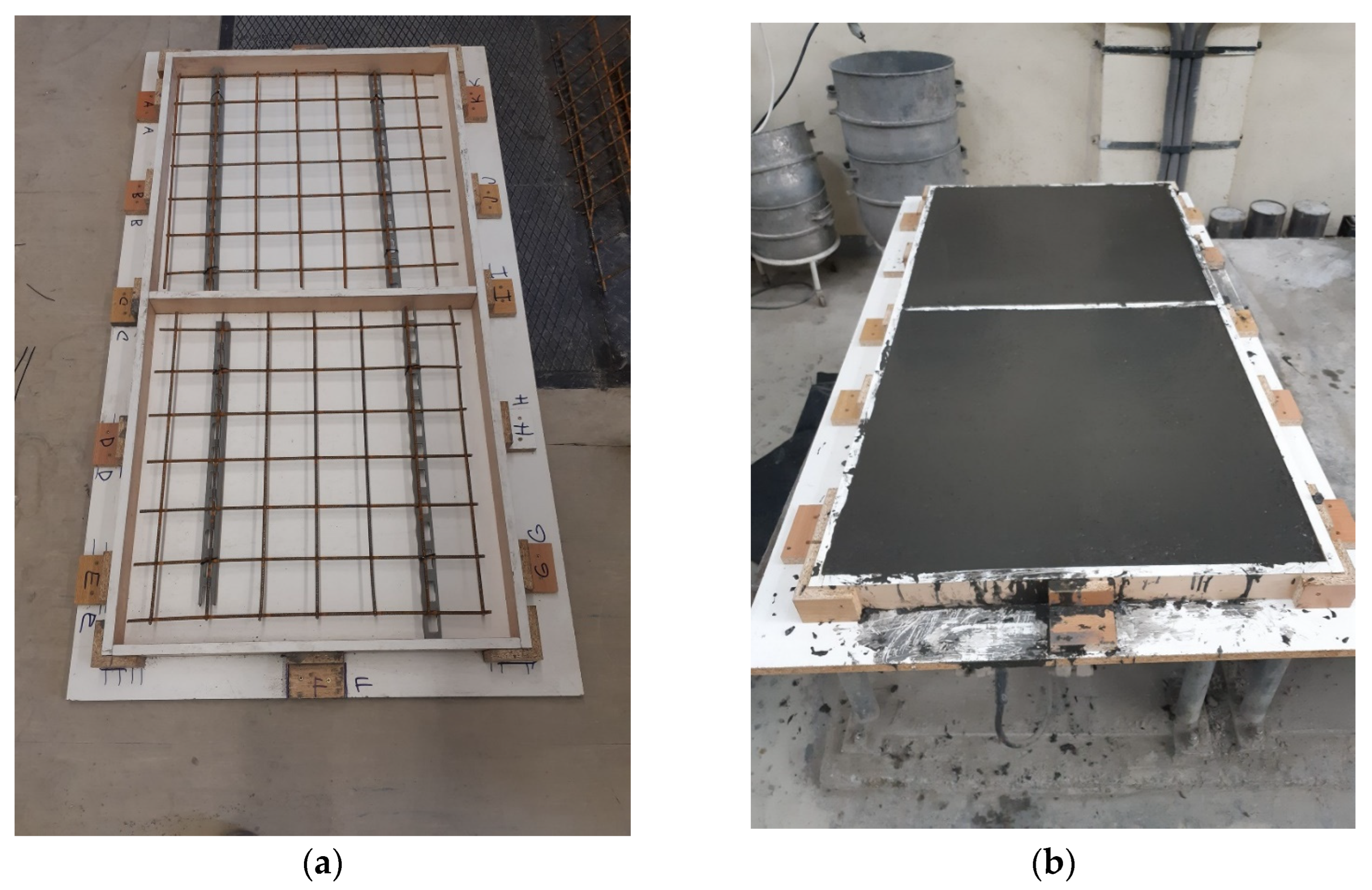
Figure 1. Preparation of the A3 batch slabs: (a) Reinforcement with B500A Ø6/100 × 100 steel mesh; (b) finished concreting of the slab.
Figure 1. Preparation of the A3 batch slabs: (a) Reinforcement with B500A Ø6/100 × 100 steel mesh; (b) finished concreting of the slab.

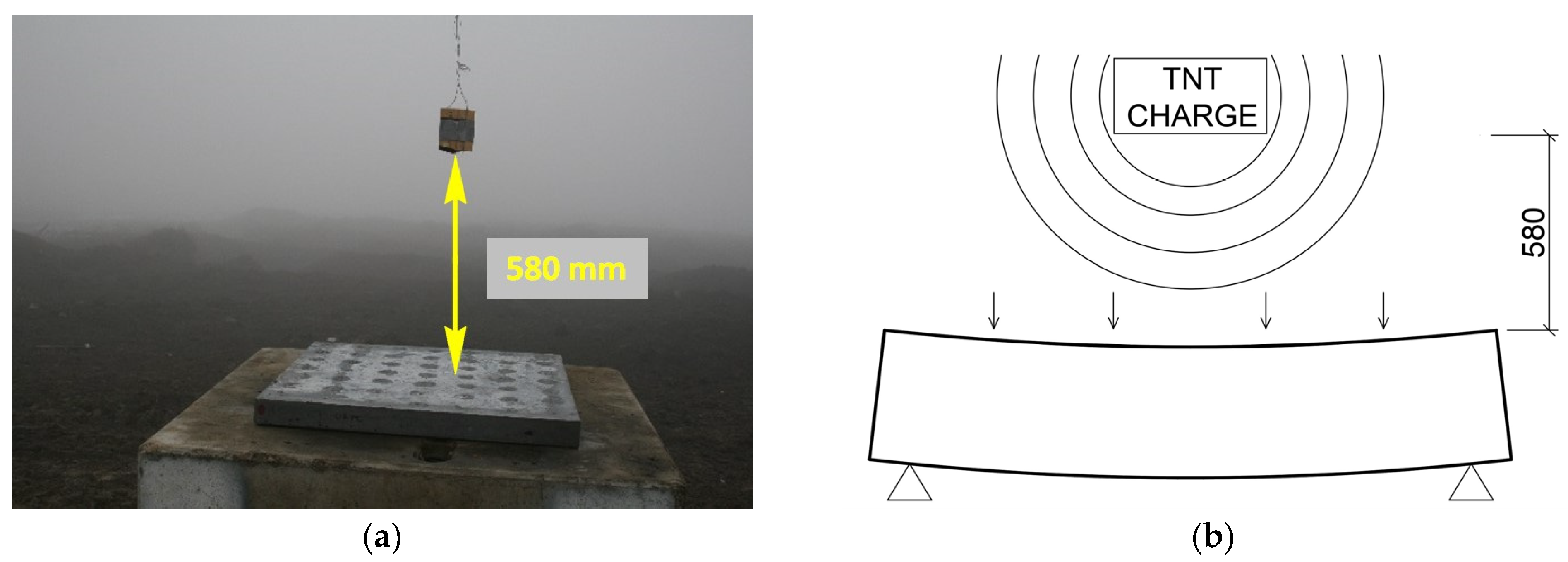
Figure 2. Experimental setup: (a) Test structure with the slab in place and a suspended 275 g TNT charge 580 mm above the surface of the slab [1]; (b) schematic diagram of the test setup.
Figure 2. Experimental setup: (a) Test structure with the slab in place and a suspended 275 g TNT charge 580 mm above the surface of the slab [1]; (b) schematic diagram of the test setup.

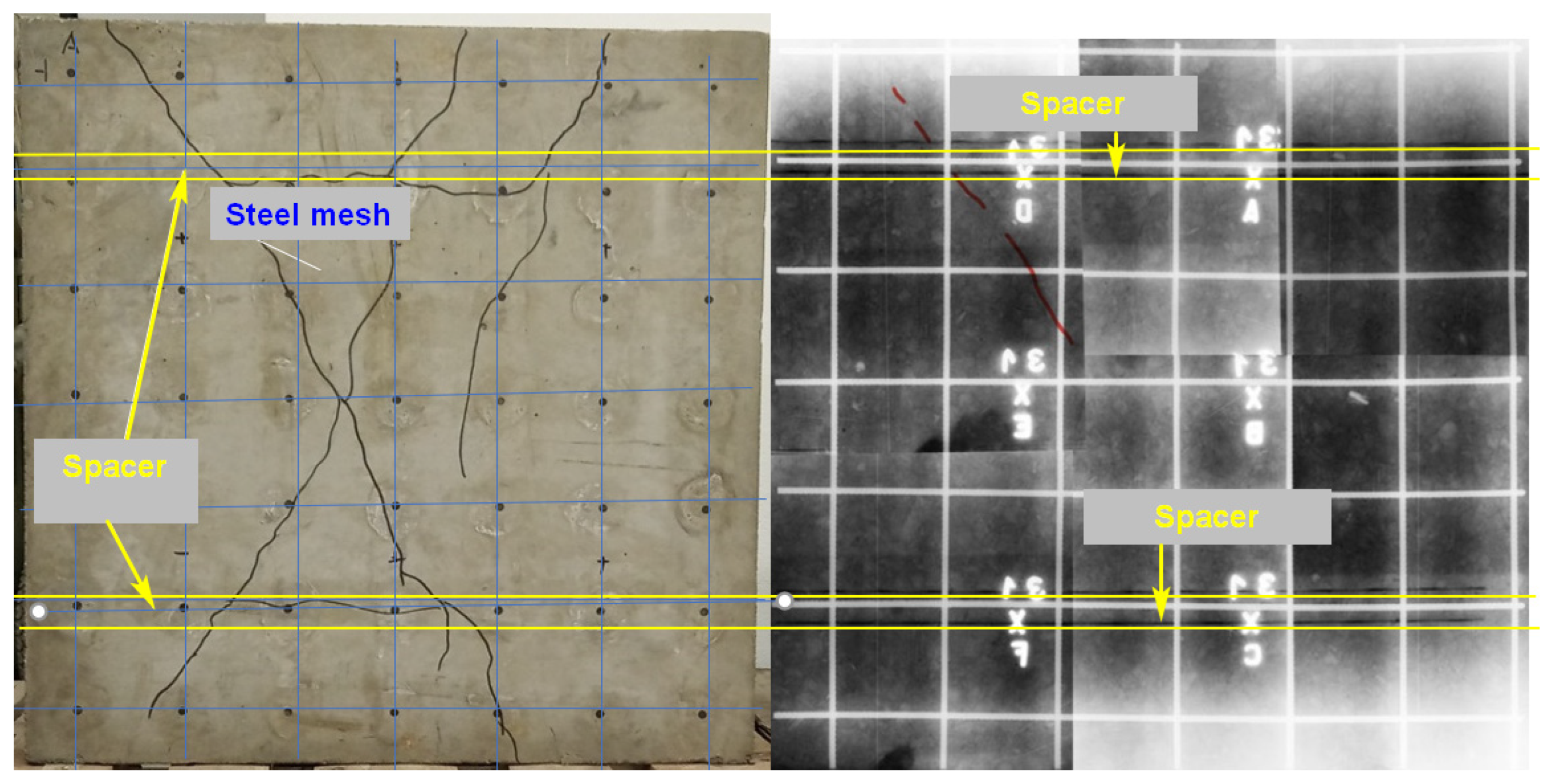
Figure 3. Slab A3_1 with cracks visually apparent compared to the only significant crack captured on the radiograph (the crack is highlighted in red on the radiograph for clarity). All pictures of the slabs shown in the article are always oriented according to the position of the first measuring point, which is located in the top left corner of the slab.
Figure 3. Slab A3_1 with cracks visually apparent compared to the only significant crack captured on the radiograph (the crack is highlighted in red on the radiograph for clarity). All pictures of the slabs shown in the article are always oriented according to the position of the first measuring point, which is located in the top left corner of the slab.

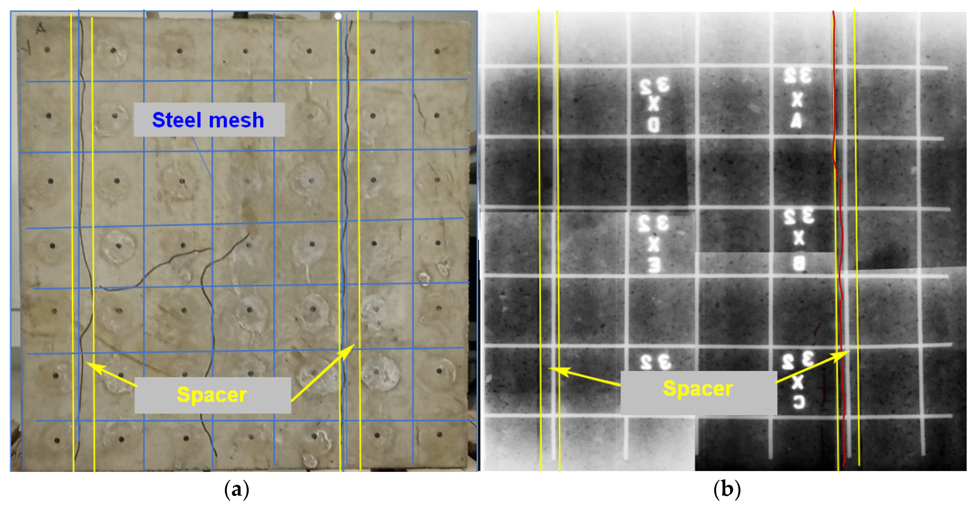
Figure 4. Comparison of results: (a) Reverse side of slab A3_2 after loading with visually visible cracks; the cracks do not correspond to the usual cracks after dynamic loading; it is likely that they are caused by the presence of reinforcement and spacers in the slab. The spacers are marked in yellow, and the reinforcement in blue. (b) Radiograph of the A3_2 slab where a more significant crack is captured in the radiograph (the crack is highlighted in red for clarity).
Figure 4. Comparison of results: (a) Reverse side of slab A3_2 after loading with visually visible cracks; the cracks do not correspond to the usual cracks after dynamic loading; it is likely that they are caused by the presence of reinforcement and spacers in the slab. The spacers are marked in yellow, and the reinforcement in blue. (b) Radiograph of the A3_2 slab where a more significant crack is captured in the radiograph (the crack is highlighted in red for clarity).

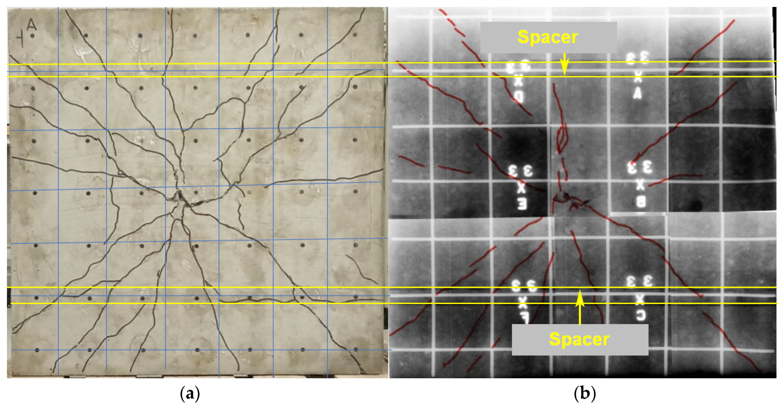
Figure 5. Comparison of results: (a) Slab A3-3 with cracks whose ray-like orientation to the corners of the slab corresponds to the dynamic loading of the slab; some transverse cracks are caused by the presence of reinforcement and spacers in the slab. (b) The radiogram of the slab shows the cracks in red, the reinforcement spacers in yellow, the reinforcement spacers in yellow, and the reinforcement of the steel mesh.
Figure 5. Comparison of results: (a) Slab A3-3 with cracks whose ray-like orientation to the corners of the slab corresponds to the dynamic loading of the slab; some transverse cracks are caused by the presence of reinforcement and spacers in the slab. (b) The radiogram of the slab shows the cracks in red, the reinforcement spacers in yellow, the reinforcement spacers in yellow, and the reinforcement of the steel mesh.

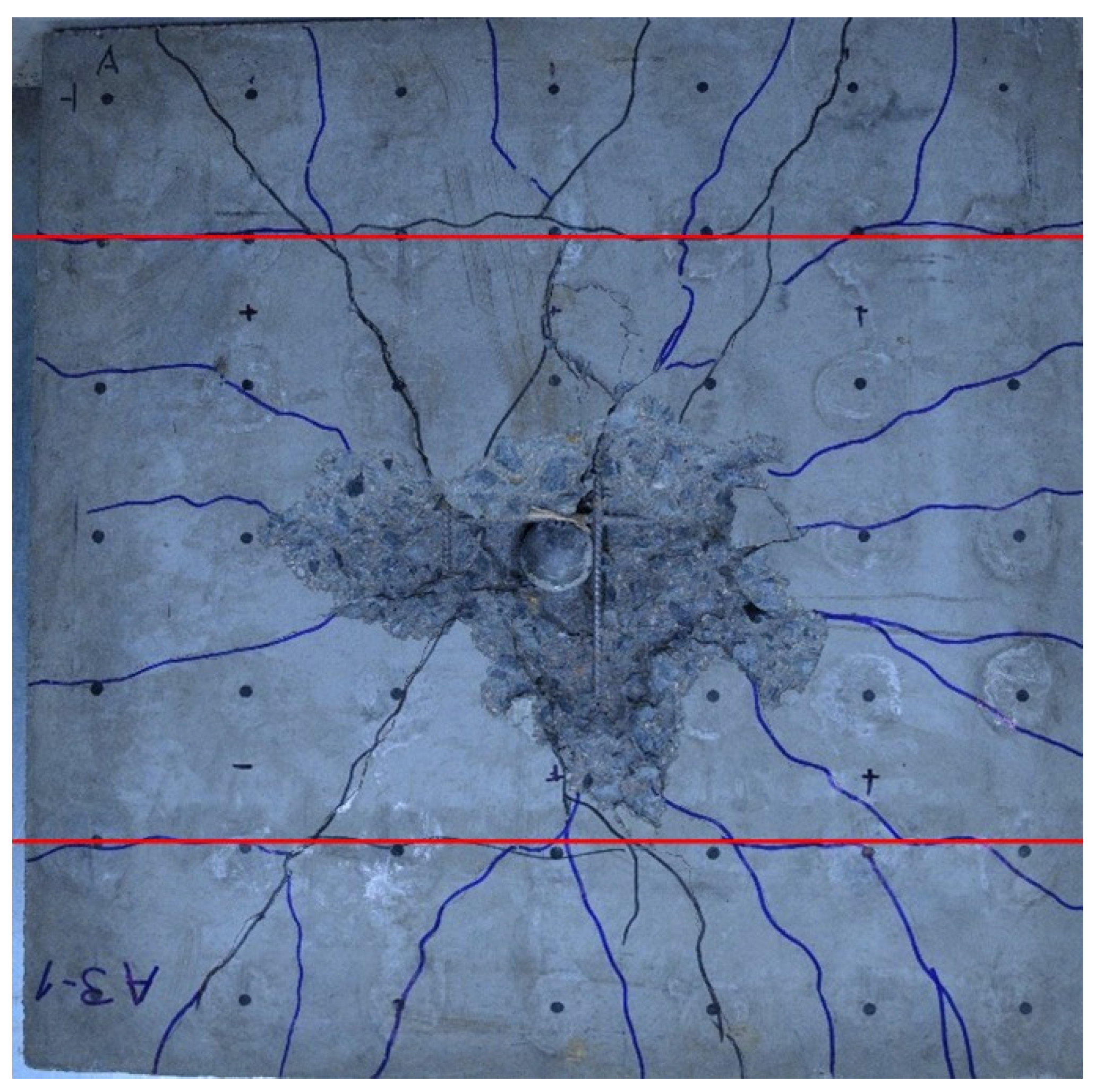
Figure 6. RC slab A3_1, loaded with 350 g TNT and subjected to an unnormalized residual strength test. The cracks at the location of the spacer are marked in red; the position of the spacers was verified by radiograph.
Figure 6. RC slab A3_1, loaded with 350 g TNT and subjected to an unnormalized residual strength test. The cracks at the location of the spacer are marked in red; the position of the spacers was verified by radiograph.

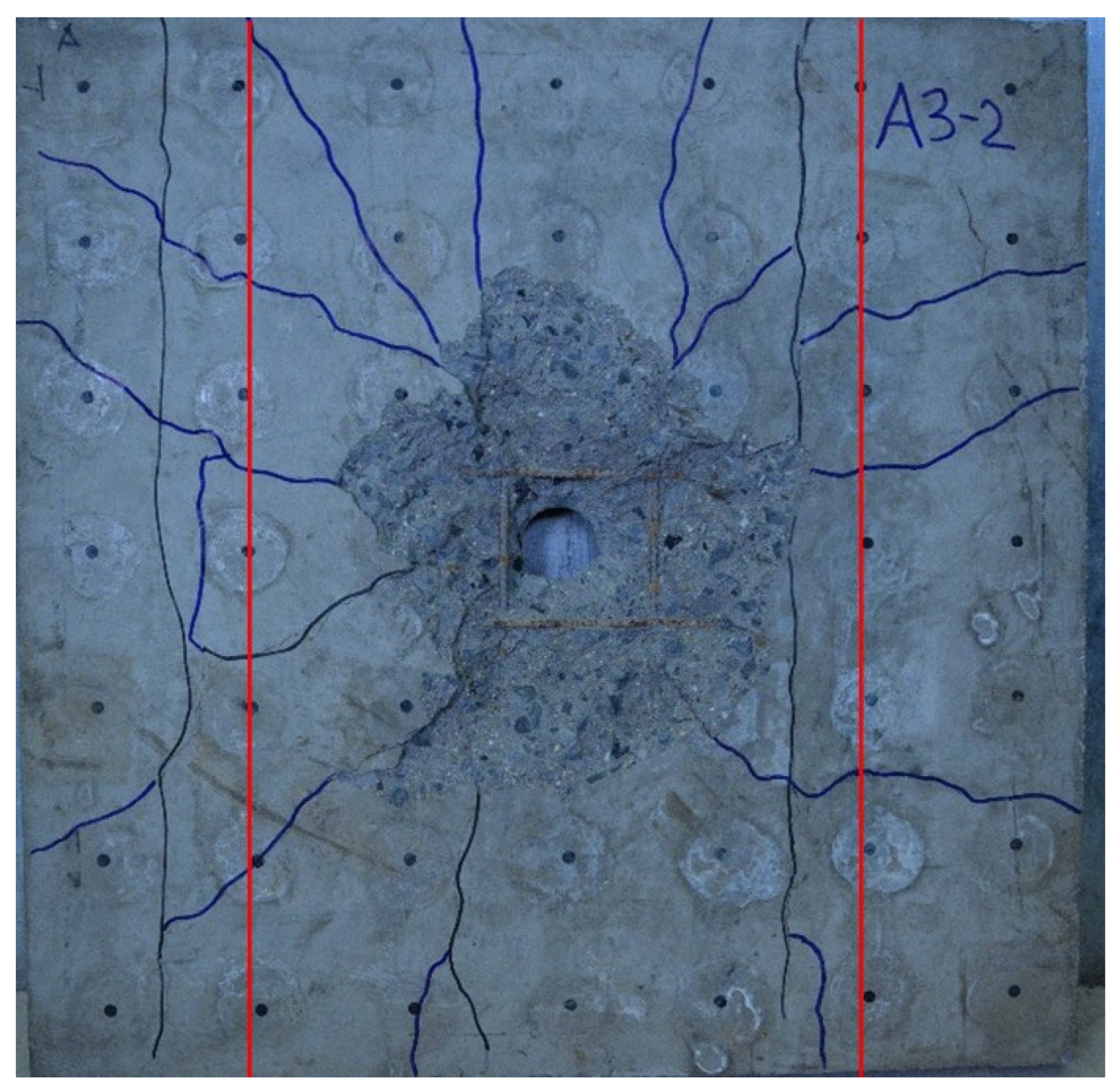
Figure 7. RC slab A3_2, loaded with 275 g TNT and subjected to an unnormalized residual strength test. The cracks at the location of the spacer are marked in red; the position of the spacers was verified by radiograph.
Figure 7. RC slab A3_2, loaded with 275 g TNT and subjected to an unnormalized residual strength test. The cracks at the location of the spacer are marked in red; the position of the spacers was verified by radiograph.

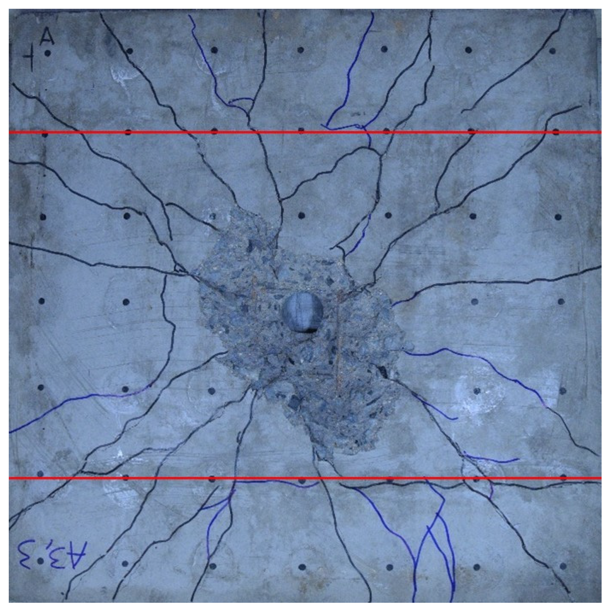
Figure 8. RC slab A3_3, loaded with 600 g TNT and subjected to an unnormalized residual strength test. The cracks at the location of the spacer are marked in red; the position of the spacers was verified by radiograph.
Figure 8. RC slab A3_3, loaded with 600 g TNT and subjected to an unnormalized residual strength test. The cracks at the location of the spacer are marked in red; the position of the spacers was verified by radiograph.

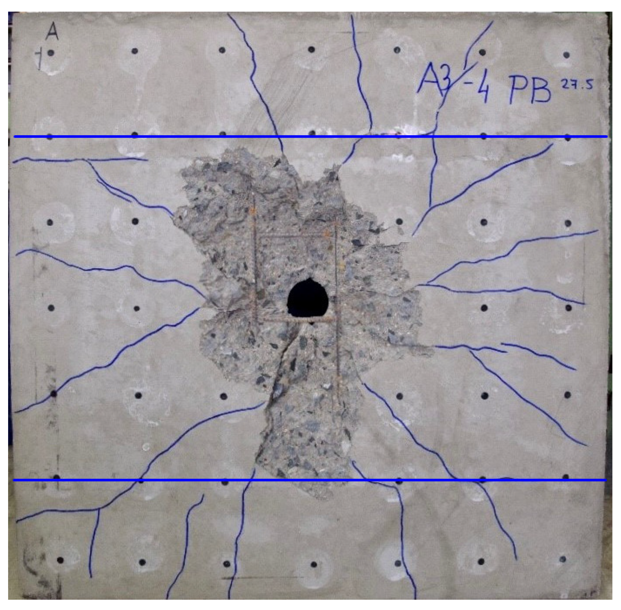
Figure 9. RC slab A3_4, not loaded by TNT explosion and only subjected to an unnormalized residual strength test. Cracks in the assumed location of the spacer are shown in blue; the spacers were not verified by X-ray.
Figure 9. RC slab A3_4, not loaded by TNT explosion and only subjected to an unnormalized residual strength test. Cracks in the assumed location of the spacer are shown in blue; the spacers were not verified by X-ray.

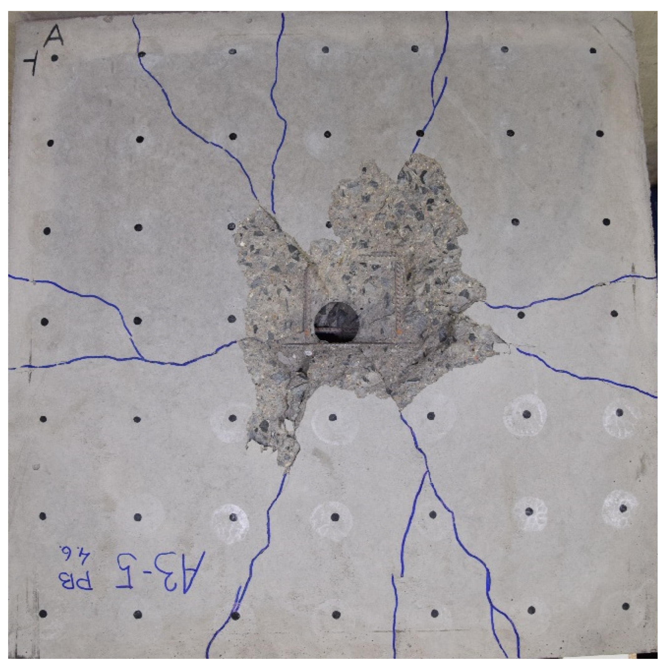
Figure 10. RC slab A3_5, not loaded by TNT explosion and only subjected to an unnormalized residual strength test. Cracks related to the spacers are not clearly visible; the placement of the spacers has not been verified by X-ray.
Figure 10. RC slab A3_5, not loaded by TNT explosion and only subjected to an unnormalized residual strength test. Cracks related to the spacers are not clearly visible; the placement of the spacers has not been verified by X-ray.

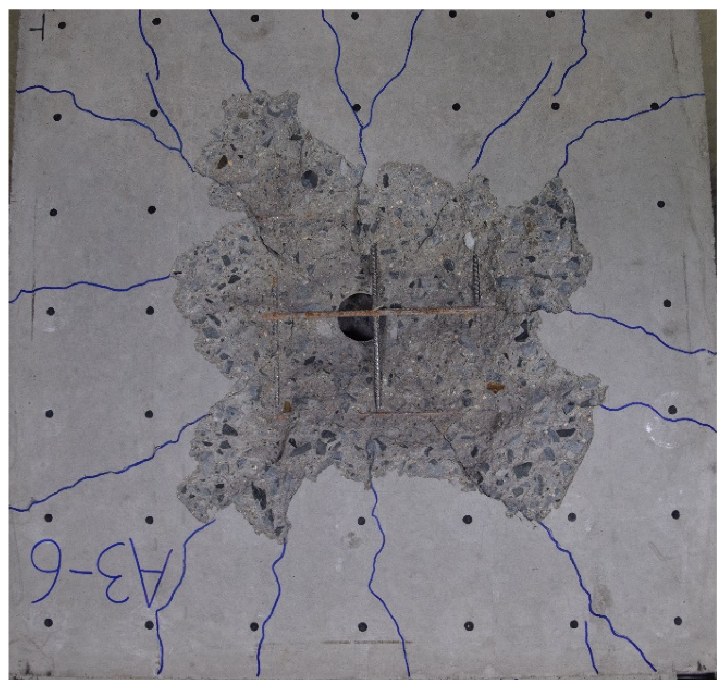
Figure 11. RC slab A3_6, not loaded by TNT explosion and only subjected to an unnormalized residual strength test. Cracks related to the spacers are not clearly visible; the placement of the spacers has not been verified by X-ray.
Figure 11. RC slab A3_6, not loaded by TNT explosion and only subjected to an unnormalized residual strength test. Cracks related to the spacers are not clearly visible; the placement of the spacers has not been verified by X-ray.

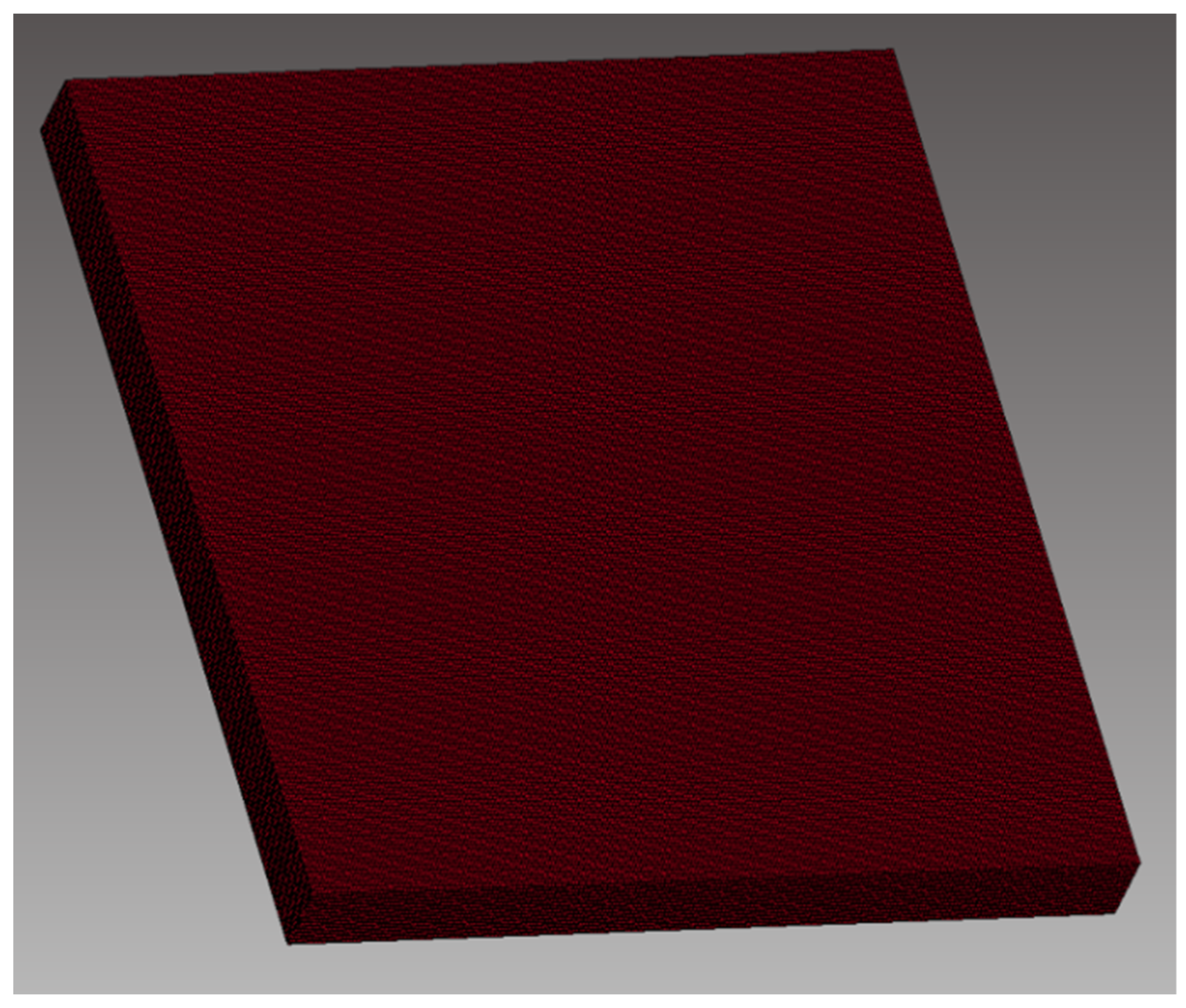
Figure 12. Concrete slab mesh—Lagrangian 8-node hexahedron solid elements with 1 integration point of the 2.5 mm edge length with RHT concrete material model assigned.
Figure 12. Concrete slab mesh—Lagrangian 8-node hexahedron solid elements with 1 integration point of the 2.5 mm edge length with RHT concrete material model assigned.

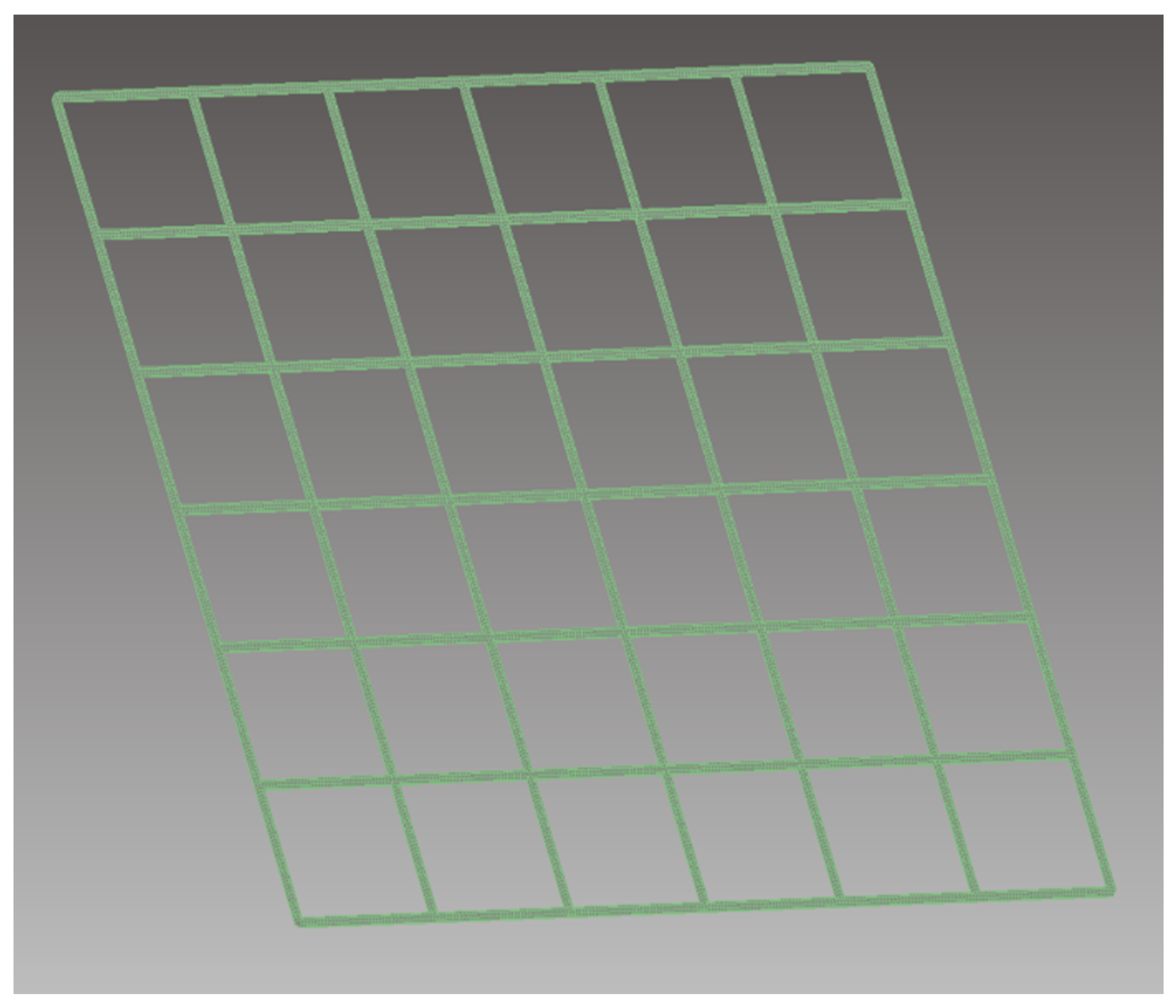
Figure 13. Reinforcement—cylindrical beam elements of diameter 6 mm with Hughes–Liu with cross-section integration element formulation with plastic kinematic material model assigned.
Figure 13. Reinforcement—cylindrical beam elements of diameter 6 mm with Hughes–Liu with cross-section integration element formulation with plastic kinematic material model assigned.

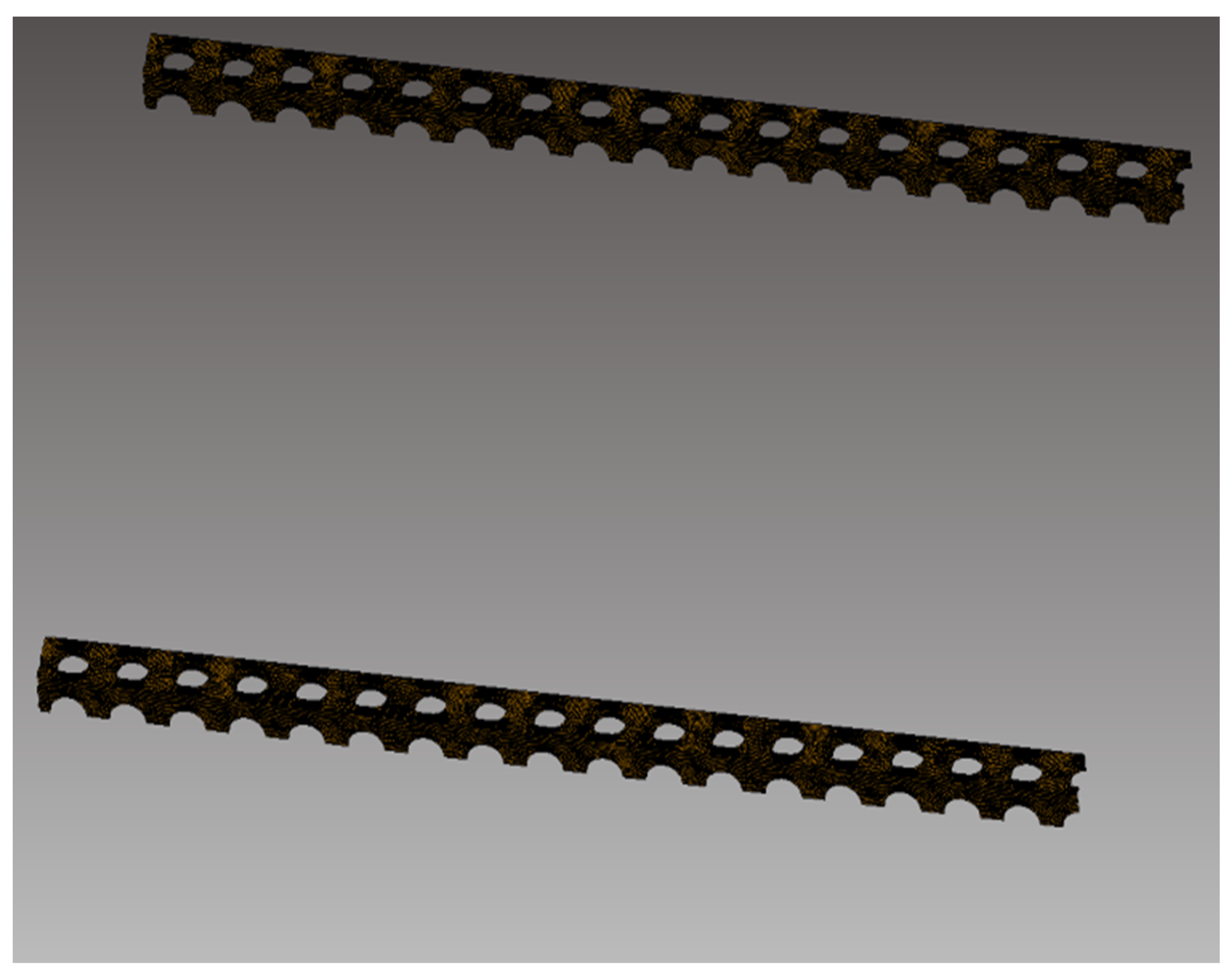
Figure 14. Meshed model of continuous plastic spacer: 2 mm thick Belytschko–Tsay 5 integration point shell elements with plastic kinematic material model assigned.
Figure 14. Meshed model of continuous plastic spacer: 2 mm thick Belytschko–Tsay 5 integration point shell elements with plastic kinematic material model assigned.

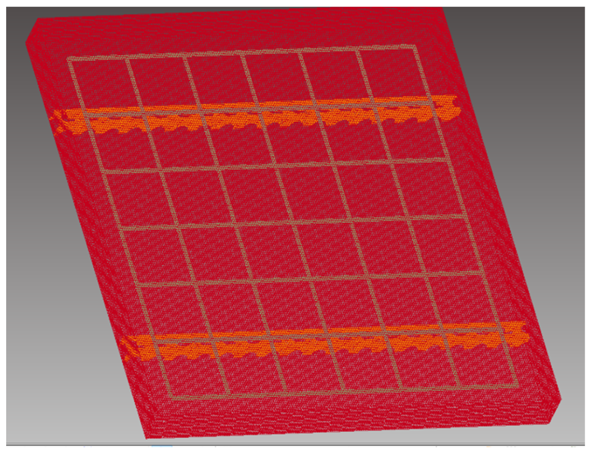
Figure 15. Concrete slab with steel reinforcement and the continuous plastic spacer–wireframe meshed element model.
Figure 15. Concrete slab with steel reinforcement and the continuous plastic spacer–wireframe meshed element model.

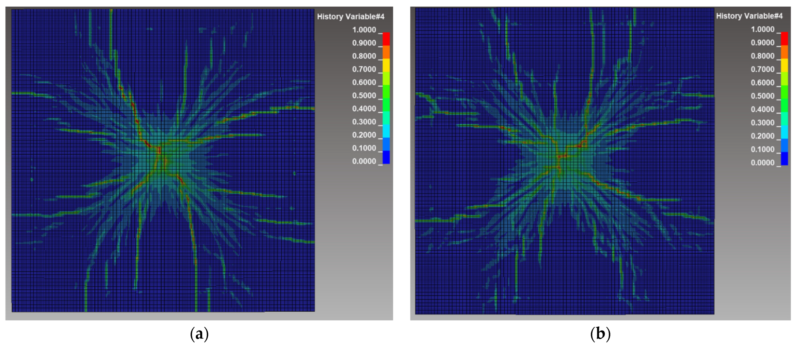
Figure 16. Modeling of the 275 g TNT blast load on the concrete slab: crack development at 2.5 ms: (a) with the continuous plastic spacer; (b) without the continuous plastic spacer.
Figure 16. Modeling of the 275 g TNT blast load on the concrete slab: crack development at 2.5 ms: (a) with the continuous plastic spacer; (b) without the continuous plastic spacer.

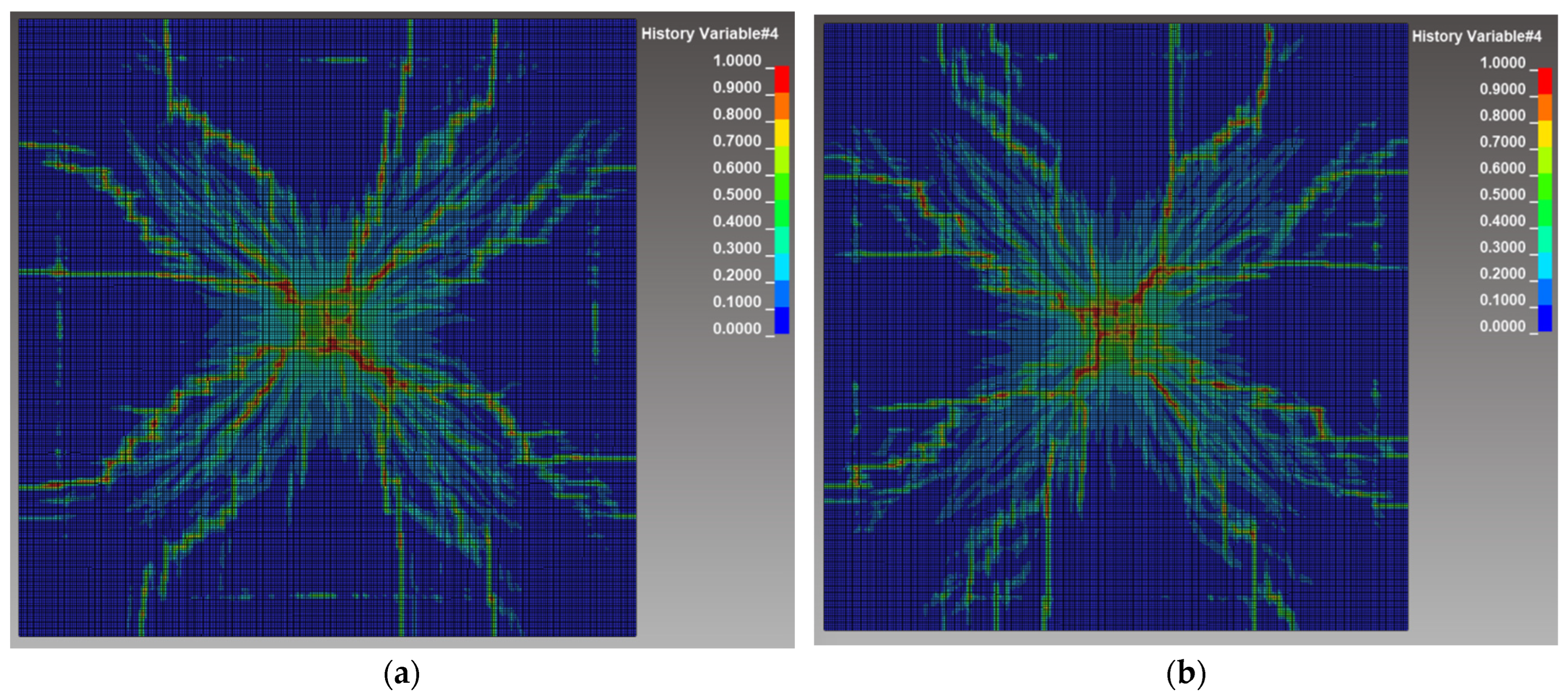
Figure 17. Modeling of the 350 g TNT blast load on the concrete slab: crack development at 2.5 ms: (a) with the continuous plastic spacer; (b) without the continuous plastic spacer.
Figure 17. Modeling of the 350 g TNT blast load on the concrete slab: crack development at 2.5 ms: (a) with the continuous plastic spacer; (b) without the continuous plastic spacer.

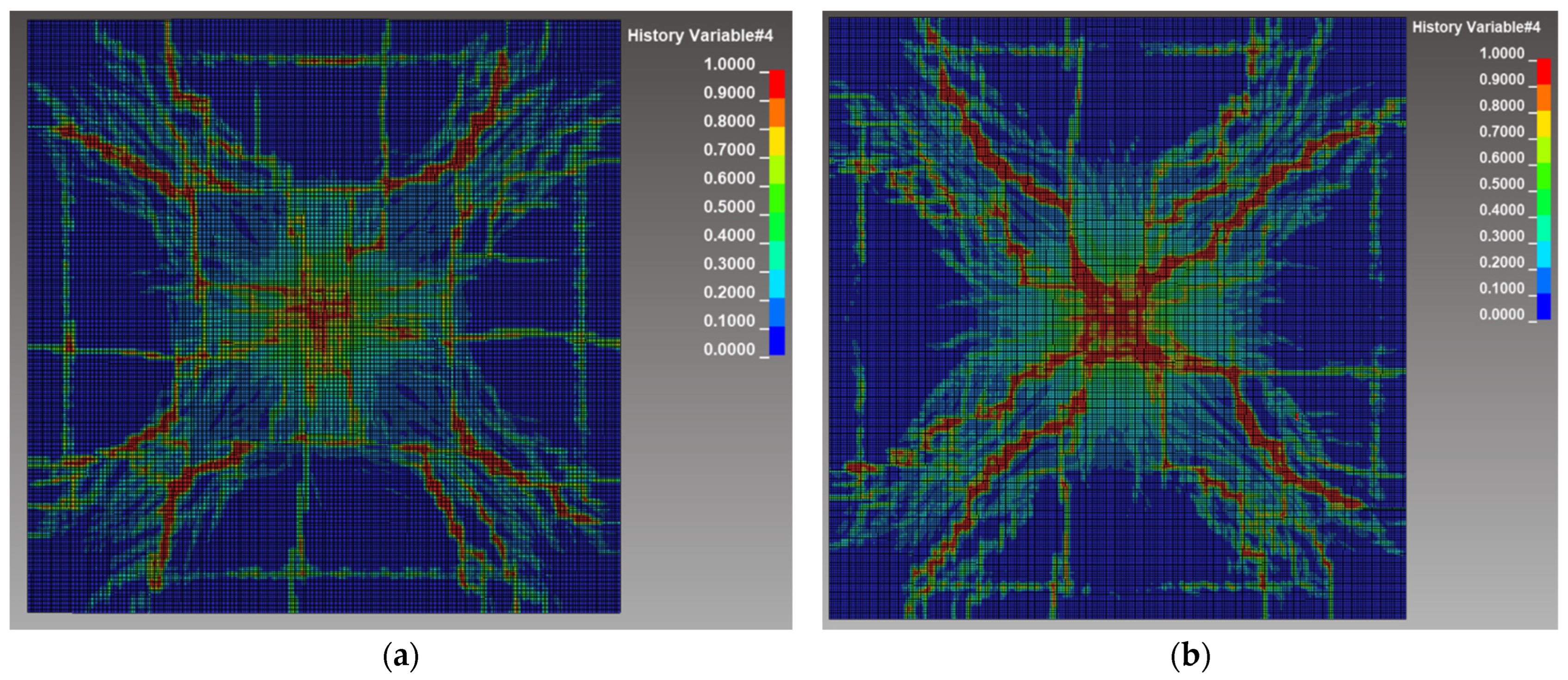
Figure 18. Modeling of the 600 g TNT blast load on the concrete slab: crack development at 2.5 ms: (a) with the continuous plastic spacer; (b) without the continuous plastic spacer.
Figure 18. Modeling of the 600 g TNT blast load on the concrete slab: crack development at 2.5 ms: (a) with the continuous plastic spacer; (b) without the continuous plastic spacer.


| Marking of Samples | A3 (RC) | |
|---|---|---|
| Cement 42.5 R—Wet | 455 | |
| Water | 165 | |
| Water/cement ratio | 0.36 | |
| Type of aggregate | Quartz | |
| Aggregate fractions | 0–4 | 880 |
| 4–8 | 220 | |
| 8–16 | 660 | |
| Superplasticizer | 4.55 (Stachement 787) | |
| Reinforcement | B500A steel mesh Ø6/100 × 100 | |

Table 2. Compressive strength of test cubes 150 mm × 150 mm × 150 mm for A3 batch, compressive strength class of concrete C 50/60.
Table 2. Compressive strength of test cubes 150 mm × 150 mm × 150 mm for A3 batch, compressive strength class of concrete C 50/60.
| Specimen No. | Specimen ID | Length | Height | Width | Weight | Density | Force | Compressive Strength |
|---|---|---|---|---|---|---|---|---|
| (–) | (–) | (mm) | (mm) | (mm) | (g) | (kg/m 3 ) | (kN) | (MPa) |
| 1 | A3-1K | 150.4 | 150.2 | 150.2 | 7965 | 2347 | 1372.32 | 60.7 |
| 2 | A3-2K | 149.5 | 148.0 | 149.3 | 7900 | 2392 | 1679.06 | 75.9 |
| 3 | A3-3K | 149.6 | 150.9 | 149.5 | 8010 | 2375 | 1569.77 | 69.6 |
| 4 | A3-4K | 149.1 | 146.4 | 149.2 | 7635 | 2345 | 1499.76 | 68.7 |
| 5 | A3-5K | 149.2 | 151.1 | 149.0 | 7940 | 2365 | 1603.85 | 71.2 |
| Average | 2365 ± 55 | 69.2 ± 3.0 |

Table 3. Flexural strength of test beams 100 mm × 100 mm × 400 mm for A3 batch, compressive strength class of concrete C 50/60.
Table 3. Flexural strength of test beams 100 mm × 100 mm × 400 mm for A3 batch, compressive strength class of concrete C 50/60.
| Specimen No. | Specimen ID | Width | Height | Length | Weight | Density | Force | Flexural Strength |
|---|---|---|---|---|---|---|---|---|
| (–) | (–) | (mm) | (mm) | (mm) | (g) | (kg/m 3 ) | (kN) | (MPa) |
| 6 | A3-6 | 100.7 | 100.6 | 400.0 | 9325.9 | 2333 | 7.56 | 5.9 |
| 7 | A3-7 | 97.1 | 100.1 | 399.9 | 9214.4 | 2337 | 8.13 | 6.5 |
| 8 | A3-8 | 98.2 | 99.7 | 400.0 | 9327.9 | 2339 | 6.75 | 5.4 |
| Average | 2335 ± 54 | 5.9 ± 0.17 |

| Slab Batch | Mark | TNT Blast Load |
|---|---|---|
| A3 (RC) | A3_1 | 350 g |
| A3_2 | 275 g | |
| A3_3 | 600 g |

Table 5. RHT material model parameters and their values for concrete compressive strength of 69 MPa (consistent system units: kg, mm, ms, kN, GPa, and kN.mm for energy).
Table 5. RHT material model parameters and their values for concrete compressive strength of 69 MPa (consistent system units: kg, mm, ms, kN, GPa, and kN.mm for energy).
| Parameter | Value | Parameter | Value |
|---|---|---|---|
| Mass density (kg/mm 3 ) | 2.365 × 10 −6 | Yield surface parameter gty | 7.0 × 10 −1 |
| Shear modulus (GPa) | 1.8436 × 10 1 | Shear reduction factor xi | 5.0 × 10 −1 |
| Eroding plastic strain e | 0.00 | Damage parameter D1 | 4.0 × 10 2 |
| Failure surface parameter A | 1.60 | Damage parameter D2 | 1.00 |
| Failure surface exponent n | 6.1 × 10 −1 | Residual damaged strain epm | 1.00 × 10 −2 |
| Compressive strength fc (GPa) | 6.9 × 10 −2 | Residual surface parameter Af | 1.60 |
| Relative shear strength fs | 1.8 × 10 −1 | Residual surface parameter nf | 6.1 × 10 −1 |
| Relative tensile strength ft | 1.0 × 10 −1 | EOS parameter B0 | 1.22 |
| Lode angle dependence parameter Qo | 6.8 × 10 −1 | EOS parameter B1 | 1.22 |
| Lode angle dependence parameter B | 1.05 × 10 −2 | EOS parameter T1 | 3.527 × 10 1 |
| Compressive reference strain rate e0c | 3.0 × 10 −8 | EOS parameter T2 | 0.00 |
| Tensile reference strain rate e0t | 3.0 × 10 −9 | Gruneisen gamma | 0.00 |
| Compressive break strain rate ec | 1.0 × 10 27 | Hugoniot parameter A1 (GPa) | 3.527 × 10 1 |
| Tensile break strain rate et | 1.0 × 10 27 | Hugoniot parameter A2 (GPa) | 3.958 × 10 1 |
| Compressive strain rate exponent bc | 1.7621 × 10 −2 | Hugoniot parameter A3 (GPa) | 9.04 |
| Tensile strain rate exponent bt | 2.2472 × 10 −2 | Crush pressure pel (GPa) | 4.5967 × 10 −2 |
| Compressive continuity parameter gc | 4.0582 × 10 −9 | Compaction pressure pco (GPa) | 6.00 |
| Tensile continuity parameter gt | 6.2844 × 10 9 | Compaction exponent N | 3.00 |
| Yield surface parameter gcy | 5.3 × 10 −1 | Initial porosity α0 | 1.1570 |

| Parameter’s Name | Mass Density | Young’s Modulus | Poisson Ratio | Yield Tress | Tangent Modulus | Failure Strain |
|---|---|---|---|---|---|---|
| (unit) | (kg/m 3 ) | (GPa) | (–) | (GPa) | (GPa) | (–) |
| Parameter’s value | 7860 | 203 | 0.30 | 0.95 | 3.00 | 0.45 |

| Parameter’s Name | Mass Density | Young’s Modulus | Poisson Ratio | Yield Tress | Tangent Modulus | Failure Strain |
|---|---|---|---|---|---|---|
| (unit) | (kg/m 3 ) | (GPa) | (–) | (GPa) | (GPa) | (–) |
| Parameter’s value | 1530 | 9.80 | 0.35 | 0.055 | 0.11 | 0.45 |

| Linear Polynomial EOS | Null Material | |||
|---|---|---|---|---|
| C4 | C5 | E0 | V0 | ρ |
| (–) | (–) | (J/m 3 ) | (–) | (kg/m 3 ) |
| 0.4 | 0.4 | 253.4 × 10 3 | 1 | 1.225 |
Where C4 and C5 are the constants of the linear polynomial EOS, E0 is the initial internal energy per unit reference volume, V0 is the initial relative volume, and ρ is the density of the air.

| Jones–Wilkins–Lee Equation of State | High-Explosive Burn Material | ||||||||
|---|---|---|---|---|---|---|---|---|---|
| A | B | R1 | R2 | ω | E0 | V0 | ρ | D | Pcj |
| (GPa) | (GPa) | (–) | (–) | (–) | (J/m 3 ) | (–) | (kg/m 3 ) | (m/s) | (GPa) |
| 3.712 | 3.231 | 4.15 | 0.95 | 0.3 | 7 × 10 9 | 1 | 1590 | 6930 | 21 |
The explosive material’s equation of state (EOS) involves the constant parameters A, B, R1, R2, and ω. Detonation energy per unit volume (E0), initial relative volume (V0), mass density of TNT explosive (ρ), detonation velocity (D), and Chapman–Jouguet pressure (Pcj) are also part of this equation.
Disclaimer/Publisher’s Note: The statements, opinions and data contained in all publications are solely those of the individual author(s) and contributor(s) and not of MDPI and/or the editor(s). MDPI and/or the editor(s) disclaim responsibility for any injury to people or property resulting from any ideas, methods, instructions or products referred to in the content.
© 2023 by the authors. Licensee MDPI, Basel, Switzerland. This article is an open access article distributed under the terms and conditions of the Creative Commons Attribution (CC BY) license (https://creativecommons.org/licenses/by/4.0/).
Zezulová, E.; Dubec, B.; Dvořák, P.; Fládr, J.; Cibulová, K. The Effect of Bottom Reinforcement Spacers on Reinforced Concrete Structures Loaded by Explosion. Buildings 2023, 13, 2963. https://doi.org/10.3390/buildings13122963
AMA StyleZezulová E, Dubec B, Dvořák P, Fládr J, Cibulová K. The Effect of Bottom Reinforcement Spacers on Reinforced Concrete Structures Loaded by Explosion. Buildings. 2023; 13(12):2963. https://doi.org/10.3390/buildings13122963
Chicago/Turabian Style
Zezulová, Eva, Branislav Dubec, Petr Dvořák, Josef Fládr, and Klára Cibulová. 2023. "The Effect of Bottom Reinforcement Spacers on Reinforced Concrete Structures Loaded by Explosion" Buildings 13, no. 12: 2963. https://doi.org/10.3390/buildings13122963
Note that from the first issue of 2016, this journal uses article numbers instead of page numbers. See further details here.